- 您现在的位置:买卖IC网 > Sheet目录1994 > DS1603+ (Maxim Integrated Products)IC COUNTER ELAPSED TIME 5V 7-SIP
DS1603
8 of 9
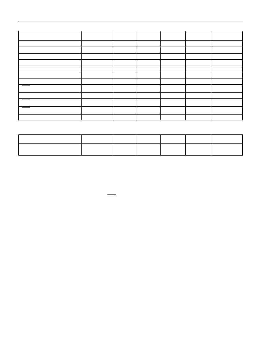
AC ELECTRICAL CHARACTERISTICS
(VCC = +5V ±10%; 0°C to +70°C)
PARAMETER
SYMBOL
MIN
TYP
MAX
UNITS
NOTES
Data to CLK Setup
tDC
50
ns
6
CLK to Data Hold
tCDH
60
ns
6
CLK to Data Delay
tCDD
200
ns
6, 7, 8
CLK Low Time
tCL
250
ns
6
CLK High Time
tCH
250
ns
6
CLK Frequency
fCLK
DC
2.0
MHz
6
CLK Rise and Fall
tF, tR
500
ns
RST
to CLK Setup
tCC
100
ns
6
CLK to RST Hold
tCCH
60
ns
6
RST
Inactive Time
tCWH
1
s
6
RST
Low to I/O High-Z
tRDZ
70
ns
6
CLK High to I/O High- Z
tCDZ
20
ns
6
(TA = +25°C)
PARAMETER
SYMBOL
MIN
TYP
MAX
UNITS
NOTES
Expected Data
Retention Time
tDR
10
years
10
NOTES:
1) All voltages are referenced to ground.
2) Logic 1 voltages are specified at a source current of 1mA.
3) Logic 0 voltages are specified at a sink current of 4mA.
4) ICC is specified with the DQ pin open.
5) ICC1 is specified with VCC at 5.0V and RST = GND.
6) Measured at VIH = 2.0V or VIL = 0.8V.
7) Measured at VOH = 2.4V or VOL - 0.4V.
8) Load capacitance = 50pF.
9) Battery trip point is the point at which the VCC powered counter and the serial port stops operation.
The battery trip point drops below the minimum once the internal lithium energy cell is exhausted.
10) The expected tDR is defined as accumulative time in the absence of VCC with the clock oscillator
running.
11) Real-time clock modules can be successfully processed through conventional wave-soldering
techniques as long as temperature exposure to the lithium energy source contained within does not
exceed +85
°C. Post-solder cleaning with water-washing techniques is acceptable, provided that
ultrasonic vibration is not used.
发布紧急采购,3分钟左右您将得到回复。
相关PDF资料
DS1642-70+
IC RAM TIMEKEEP NV 70NS 24-EDIP
DS1643P-70+
IC RAM TIMEKEEP NV 70NS 34-PCM
DS1644P-120
IC RAM TIMEKEEP NV 120NS 34-PCM
DS1646-120+
IC RAM TIMEKEEP NV 120NS 32-EDIP
DS1647P-120
IC RAM TIMEKEEP NV 120NS 34-PCM
DS1670S
IC CTRLR SYSTEM PORTABLE 20-SOIC
DS1672S-3/T&R
IC TIMEKEEPER 3V 32-BIT 8-SOIC
DS1673S-3
IC CTRLR SYSTEM PORT 3V 20-SOIC
相关代理商/技术参数
DS1603J
制造商:NSC 制造商全称:National Semiconductor 功能描述:TRI-STATE Dual Receiver
DS1603J/883
制造商:National Semiconductor Corporation 功能描述:Dual Receiver 14-Pin CDIP
DS1603N
制造商:未知厂家 制造商全称:未知厂家 功能描述:Analog Timer Circuit
DS16-03P
制造商:Cooper Bussmann 功能描述:TOP SCREW-ON INSERTION BRIDGE, 3 POLE, F - Bulk 制造商:COOPER BUSSMANN 功能描述:TOP SCREW-ON INSERTION BRIDGE, 3 POLE, F
DS1603W/883
制造商:NSC 制造商全称:National Semiconductor 功能描述:TRI-STATE Dual Receiver
DS16-04P
制造商:Cooper Bussmann 功能描述:TOP SCREW-ON INSERTION BRIDGE, 4 POLE, F - Bulk 制造商:COOPER BUSSMANN 功能描述:TOP SCREW-ON INSERTION BRIDGE, 4 POLE, F
DS1608
制造商:未知厂家 制造商全称:未知厂家 功能描述:Analog Timer Circuit
DS16083
制造商:DAL 功能描述:1608-3 DALLAS SEMI S7G6B